

Four Touch Panel Structures. Which One Fits Your Product?
When selecting a capacitive touchscreen for an industrial HMI, medical device or smart home controller, you may come across terms such as G+G, G+F, F+F and P+G.
They may look like simple abbreviations, but they describe important differences in touch sensor materials and construction.
Does G+G always mean better durability? Is G+F thinner? And what exactly does P+G mean?
Let’s explore the basic structures and what OEM customers should confirm before choosing a touch panel.
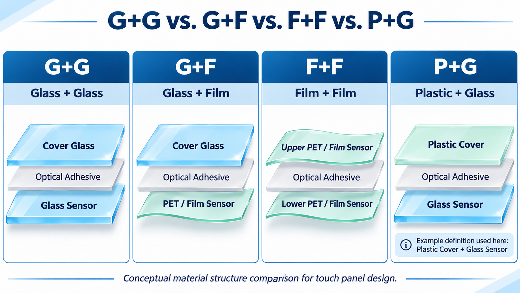
01 | G+G — Glass + Glass
A typical G+G capacitive touch panel uses a protective glass cover and a separate glass-based touch sensor.
The layers are joined using a suitable optical adhesive.
Typical structure: Cover Glass + Optical Adhesive + Glass Touch Sensor.
Key characteristics:
- Rigid glass-based construction
- Good dimensional stability
- Suitable for applications requiring a solid front structure
- Potentially greater weight and thickness than film-based alternatives
G+G may be considered for industrial control panels, instruments and other equipment where a rigid glass-based design is appropriate.
02 | G+F — Glass + Film
A typical G+F structure combines a protective glass cover with a film-based capacitive touch sensor.
The film commonly uses a transparent conductive material such as ITO.
Typical structure: Cover Glass + Optical Adhesive + Film Touch Sensor.
Key characteristics:
- Uses a flexible film sensor substrate
- Can reduce sensor weight compared with glass-based designs
- Offers different thickness and cost possibilities
- Touch performance depends on electrode pattern and controller design
G+F should not automatically be described as single-touch only. The actual number of supported touch points depends on the sensor architecture and controller.
03 | F+F — Film + Film
F+F commonly describes a touch sensor arrangement using two conductive film layers.
These films can provide separate electrode directions for capacitive touch detection.
Typical sensor structure: Film Sensor + Optical Adhesive + Film Sensor.
When a glass cover is added, the complete assembly is commonly described as G+F+F or GFF.
Key characteristics:
- Thin and lightweight sensor substrates
- Suitable for certain compact or weight-sensitive designs
- Supports multiple electrode layout options
- Requires careful evaluation of film materials, lamination and environmental reliability
The final mechanical strength depends on the complete touchscreen assembly, including its protective cover.
04 | P+G — Plastic + Glass
P+G is less consistently defined across the touchscreen industry.
In one common convention, it means a plastic cover lens combined with a glass touch sensor.
Possible plastic cover materials include PC or PMMA.
Other suppliers may use P+G to describe different PET and glass sensor combinations.
Important: Confirm what the P and G layers represent in the supplier’s actual drawing before making technical or purchasing comparisons.
Potential considerations:
- Cover material and surface hardness
- Weight and mechanical design
- Scratch resistance
- UV and environmental durability
- Sensor construction and optical performance
A plastic cover does not automatically provide the same scratch resistance or long-term outdoor behavior as a glass cover.
05 | Comparing the Four Touch Structures
| Structure | Typical Materials | Main Consideration |
|---|---|---|
| G+G | Glass cover + glass sensor | Rigid construction and dimensional stability |
| G+F | Glass cover + film sensor | Weight, thickness and electrode design |
| F+F | Two film sensor layers | Flexible sensor construction; cover lens specified separately |
| P+G | Often plastic cover + glass sensor | Confirm supplier definition and surface durability |
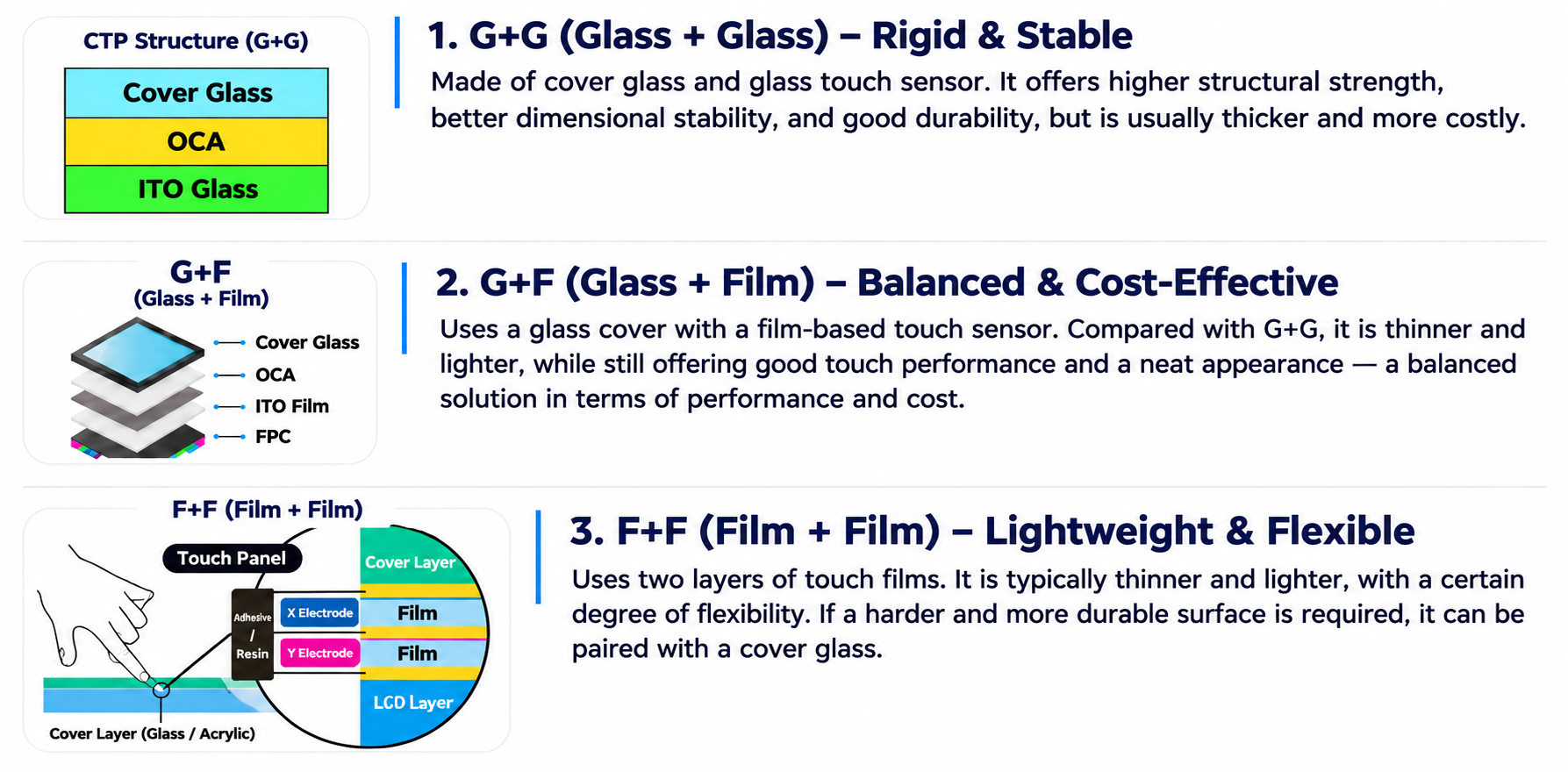
No single structure guarantees the lowest cost, best transparency or highest touch accuracy for every product.
Final performance depends on the materials, electrode design, touch controller, bonding process and complete assembly.
06 | Does Touch Structure Determine Optical Bonding?
No. Touch panel construction and display bonding are different design decisions.
G+G or G+F describes the structure of the touch panel.
Optical bonding describes how the touch assembly is joined to the LCD module.
Depending on the selected design, a touch panel may be integrated with the LCD through an air-gap structure or suitable optical bonding.
07 | Frequently Asked Questions
Is G+G always better than G+F?
No. G+G offers a rigid glass-based structure, while G+F can provide film-related weight and thickness advantages. The better option depends on the application.
Can G+F support multi-touch?
Potentially, yes. The number of touch points depends on the sensor electrode architecture, controller IC and firmware, not only the G+F label.
What is the difference between F+F and G+F+F?
F+F usually describes the two-film sensor structure. G+F+F describes a complete touch structure with an additional glass cover lens.
What does P+G mean?
It often refers to a plastic cover lens and glass sensor, but supplier terminology varies. Always request the cross-sectional structure and material specifications.
Does G+G automatically provide better outdoor performance?
No. Outdoor performance also depends on the cover treatment, UV resistance, optical bonding, sealing and environmental validation.
Can Future Display review custom touch-panel requirements?
Future Display can discuss suitable touch integration, cover glass, FPC and TFT LCD requirements for customized display projects. Available structures and production feasibility require engineering confirmation.
08 | RFQ: How to Specify Your Capacitive Touch Panel
Choosing a touchscreen for a new industrial HMI or smart device?
Share your requirements with Future Display so our team can review suitable configurations.
Custom Touch Panel RFQ Checklist
Application: Industrial HMI / Medical / Smart Home / Instrument / Other
Display Size: Required diagonal and outline dimensions
Preferred Structure: G+G / G+F / F+F / P+G / To Be Evaluated
Cover Lens: Glass or plastic material, thickness and surface treatment
Touch Functions: Number of touch points, gestures and glove operation
Controller & Interface: Touch IC, I2C / USB or host requirements
Bonding: Air Gap / Optical Bonding / To Be Evaluated
Environment: Temperature, humidity, water exposure and UV requirements
Mechanical Design: FPC, connector and cover-glass drawing
Purchase Plan: Sample quantity, annual demand and schedule
Request Engineering Review & Quotation
Email: info@futurelcd.com
Online Inquiry: Contact Future Display
Send your drawings and application details to discuss suitable touch and display integration options.
Conclusion: Choose the Structure, Not Just the Abbreviation
G+G, G+F, F+F and P+G describe important differences in capacitive touchscreen construction.
But the best solution depends on the complete product requirements, including optical performance, weight, surface durability, controller compatibility and environmental conditions.
Before approving a touch panel, confirm the full layer structure and the final display assembly.
Future Display | Custom TFT LCD & Touch Solutions
Post time: Nov-16-2026


